
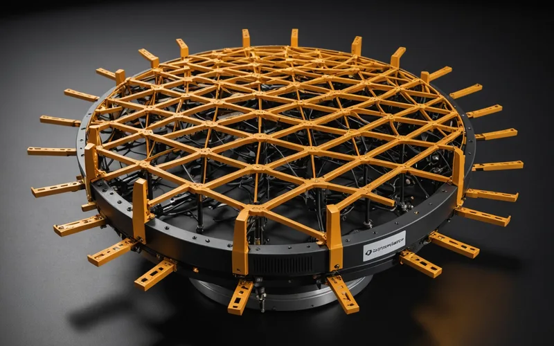
A 64-element mmWave active antenna unit dissipates heat from 64 individual PA elements in a volume that, depending on the beamforming architecture, may be smaller than a hardcover book. That physical constraint is the starting point for understanding why GaAs PA technology, despite its maturity and established supply chain, creates a structural problem for 5G massive MIMO active antennas.
This article covers the thermal and efficiency constraints that define the PA requirements for 5G massive MIMO at mmWave, where GaAs can and cannot meet those requirements, and where GaN-on-SiC changes the equation. We are not arguing that GaAs is obsolete. The claim is specific: at the element count and element density required for mmWave beamforming above 24 GHz, GaAs efficiency is a binding constraint that shapes system architecture choices in ways that would not be necessary with a more efficient process.
The Density Problem in Massive MIMO Active Antennas
In a massive MIMO active antenna unit (AAU), each antenna element has an associated PA and LNA in the transmit and receive path respectively. At 28 GHz, half-wavelength element spacing is approximately 5.4 mm. A 64-element panel at 28 GHz with lambda/2 spacing is roughly 230 mm x 30 mm at minimum, depending on how the elements are arranged in a 2D or 1D array.
Within that footprint, the thermal management challenge is that PA dissipation is distributed across 64 points. There is no single hot spot to manage; there is a thermal field. If each GaAs PA element at 28 GHz delivers 250 mW output RF power at 25% drain efficiency, it dissipates 750 mW. Sixty-four elements dissipate 48W in total. At 5.4 mm pitch, the thermal flux density at the back of the array substrate reaches levels that require either a thick copper spreader or active cooling to prevent thermal runaway in the center elements.
If efficiency rises from 25% to 45%, each element dissipates 306 mW for the same 250 mW output. Total array dissipation drops to 19.6W. The thermal flux density at center falls by more than half, and the temperature gradient across the array shrinks. That temperature gradient matters because gain and phase variation with temperature are the primary source of array pattern degradation over operational lifetime.
Why GaAs Has Structural Efficiency Limits at mmWave
GaAs operates with a supply voltage typically in the 3-5V range for mmWave PA designs. At those voltages, achieving high output power requires large gate periphery, which increases parasitic capacitance and limits achievable frequency and bandwidth. At 28 GHz, GaAs pseudomorphic high-electron-mobility transistor (pHEMT) processes achieve peak efficiency in the 20-30% range for class AB operation at realistic back-off levels. Optimized GaAs designs using Doherty or envelope tracking topologies can push this to 35-38% in controlled conditions, but those topologies add baseband complexity and are sensitive to impedance variation with temperature.
GaN-on-SiC operates at supply voltages of 28-48V, which allows higher output impedance and makes broadband matching networks more practical. The SiC substrate has thermal conductivity of approximately 400 W/m-K versus GaAs at 45 W/m-K. This means heat generated at the junction spreads laterally through the substrate much more effectively in GaN-on-SiC, reducing the peak channel temperature for the same dissipated power. Published mmWave GaN-on-SiC PA data from multiple sources consistently shows drain efficiency of 35-55% at 28 GHz under class AB or Doherty topology, depending on gate length and process maturity.
This is not saying GaAs processes cannot produce useful mmWave PAs. They clearly can, and they dominate current 5G NR handset and small-cell deployments at frequencies below 28 GHz. The efficiency comparison becomes structurally relevant at the combination of high element count, high element density, and output power per element that defines a macro-cell massive MIMO AAU.
Array-Level Efficiency and System Thermal Budget
The array-level efficiency calculation must account for the full transmit chain, not just the PA. The chain includes the beamforming IC or phase shifter network, the inter-element distribution network, connectors, and the PA itself. Insertion loss in the distribution network adds to the total DC power consumption because it lowers the net RF power delivered to the antenna element relative to what the PA produces.
For a phased array with 2 dB of distribution network loss between the PA output and the antenna element, the effective radiated efficiency is lower than the PA drain efficiency by the distribution loss factor. If the PA is 45% efficient and the distribution network contributes 2 dB of loss, the overall transmit chain efficiency from PA DC input to radiated RF is approximately 28-32%, depending on the element coupling conditions. The thermal consequence is that those 2 dB of distribution loss appear as heat in the PCB substrate, adding to the junction-level dissipation from the PA.
This full-chain perspective is why some AAU designs have moved toward antenna-integrated PA modules where the PA output port is directly connected to the radiating element with minimal distribution network. The tradeoff is tighter integration constraints and harder post-integration rework. For a team building a 64-element array for the first time, the evaluation question is whether the thermal savings from reduced distribution loss outweigh the assembly risk and the reduction in design margin.
EVM and AM-AM Flatness Across the Array
Beyond efficiency, the RF front-end designer for a massive MIMO AAU needs to satisfy the EVM requirements of 5G NR for the supported modulation orders. 3GPP TS 38.104 specifies EVM requirements for base station transmitters that range from 8% for QPSK down to 3.5% for 256QAM at the radiated beam level.
PA nonlinearity contributes to EVM through AM-AM distortion (gain compression) and AM-PM distortion (phase rotation with amplitude). In a phased array, these distortions are not the same on every element because each PA sits at a slightly different temperature depending on its position in the array and its history of recent RF activity. The temperature gradient across the array creates element-to-element variation in gain and phase that the digital pre-distortion (DPD) system must calibrate out continuously.
A PA with flatter AM-AM curves in the operating back-off range reduces the dynamic range that DPD needs to correct. GaN devices, because of the higher supply voltage and the resulting flatter load line, typically show less severe AM-AM compression below P1dB compared to GaAs. This means the initial EVM before DPD is better, and the DPD algorithm needs a smaller correction range, which reduces the calibration error when temperature drift creates variation that the DPD model did not fully capture.
Practical Implications for RF Front-End Selection
For a team designing a 5G mmWave AAU, the RF front-end selection process needs to evaluate three things simultaneously: element-level PA efficiency at the operating back-off for the required modulation, thermal resistance from junction to the thermal management surface, and AM-AM flatness in the operating range.
The element count is the multiplier that converts per-element specs into system-level consequences. At 16 elements, the difference between 25% and 45% efficiency is noticeable but manageable with moderate thermal management. At 64 elements and above, the same efficiency gap creates a system design problem that no amount of after-the-fact heatsinking resolves cleanly. The PA selection decision has to be made before the thermal management architecture is finalized, not after.
We have been working on this specific problem for the FA-2400 series, targeting a back-off efficiency profile and a junction-to-case thermal resistance that supports compact 64-element array designs without forced liquid cooling. Those are design targets based on our GaN-on-SiC architecture and our simulation work, confirmed in early characterization. We treat them as design goals, not production commitments, until the full characterization campaign is complete.